
Remote Video Links: Plan and Measure End-to-End Latency
Build a practical latency budget for remote video. Check source formats, network behaviour, SRT buffering and receiving equipment before selecting an encoder.
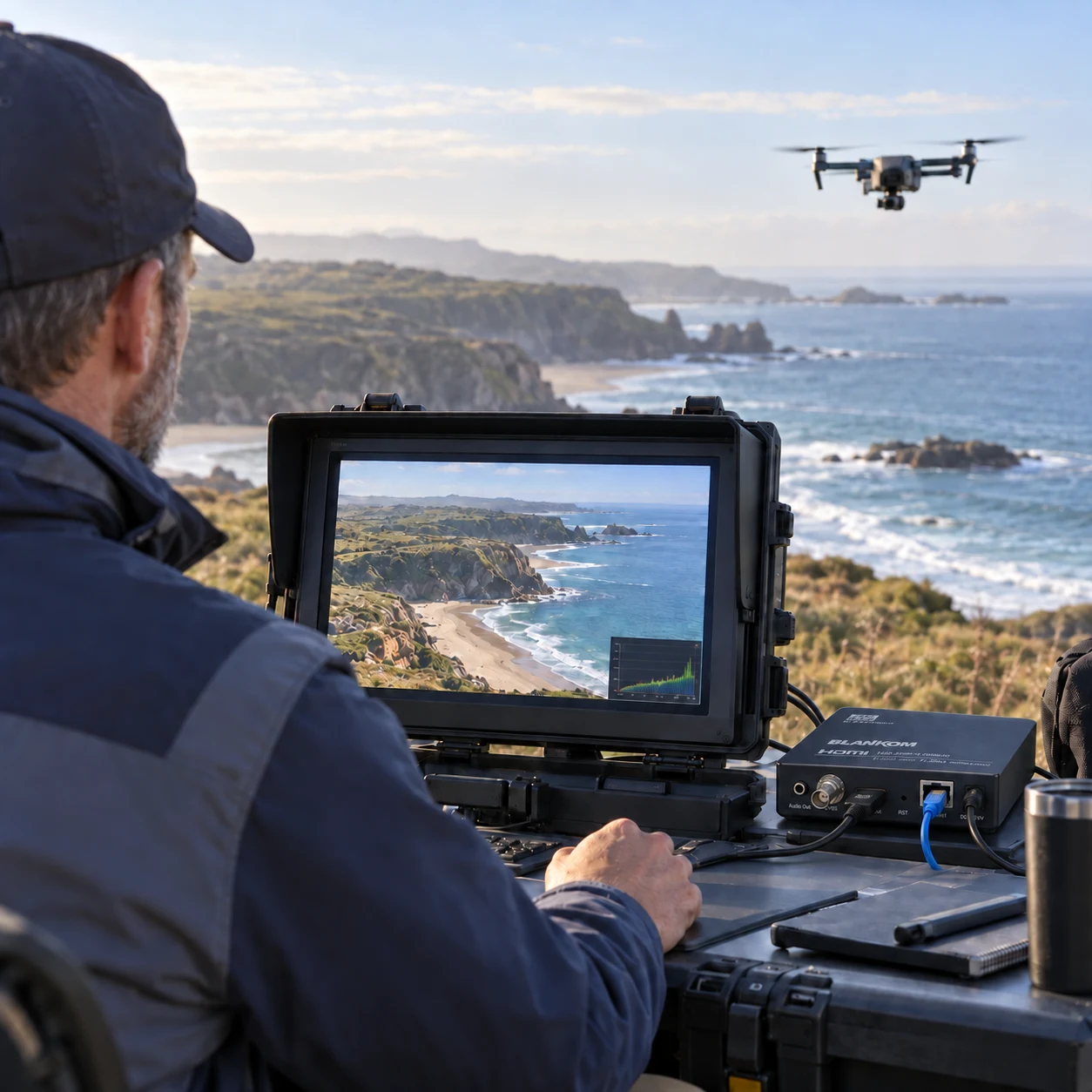
Start with the complete video path
A useful latency requirement describes what the viewer experiences: the time from an event in front of the camera to the same event on the receiving display. A transport setting alone does not describe this result. Camera processing, encoding, transport, decoding and display processing all contribute. SRT latency documentation explains this distinction.
Write down the intended viewing task and agree a measurable acceptance criterion before selecting hardware. Record the camera output, the receiving application and the display mode. Keep a separate requirement for image quality, because reducing delay at the expense of unreadable detail may not meet the project brief.
Make a latency budget you can test
Assign a working allowance to each stage, then replace assumptions with measurements as the system becomes available. Keep the video format and software versions alongside the result so that later changes can be compared fairly.
| Stage | Record | How to isolate it |
|---|---|---|
| Source | Format and processing mode | Compare the source with its local output |
| Encode / decode | Codec settings and elapsed delay | Use a controlled local network first |
| Network | RTT, variation, packet loss and load | Repeat during representative busy periods |
| Player / display | Buffer and display mode | Compare the intended receiver configurations |
| Complete path | Observed delay and interruptions | Measure source event and displayed event together |
Choose SRT settings from observed conditions
SRT uses receiver buffering to accommodate variable packet arrival and retransmission. Increasing this allowance can provide more recovery time but also increases waiting time; reducing it leaves less time for recovery. Keep the measured end-to-end result separate from the configured SRT latency. SRT latency documentation describes the buffering mechanism.
Record RTT, packet loss, retransmissions and late or dropped packets while the actual stream is running. Test the expected range of network conditions, not just an idle speed test. Change one setting at a time and keep the before-and-after results.
The sending rate needs room for retransmitted traffic as well as the original stream. The SRT protocol documentation describes bandwidth overhead controls. A higher bandwidth limit cannot create capacity on a congested link. If the path cannot sustain the traffic, revisit the stream bitrate, the network capacity or the required operating conditions.
Check both endpoints before choosing the encoder
Create a compatibility sheet for the source and receiver. Include the physical interface, resolution, frame rate, codec and profile, audio format, transport and stream packaging. Record whether the receiver is dedicated hardware or an application, and name its version.
For SRT, agree the connection mode, addressing and port plan with the network administrator. Confirm the encryption and key settings supported at both ends when encryption is required. Keep passwords and keys outside ordinary project worksheets.
Hardware selection also needs a separate assessment of power, mounting, temperature and environmental requirements. An encoder’s video interface or SRT support alone does not establish suitability for an airborne, marine or other demanding installation.
Use a repeatable acceptance test
- Establish a baseline. Test the complete source-to-display chain on a controlled local network.
- Use representative pictures and audio. Include movement, detailed scenes and the expected lighting conditions.
- Move to the intended network. Repeat at different traffic loads and log the duration of each run.
- Test recovery. In an authorised test environment, interrupt the connection and record reconnection time, picture recovery and any manual action.
- Save the accepted configuration. Retain device versions, settings, network notes and measured results together.
Do not report the best isolated measurement as the operating guarantee. Agree which conditions the accepted result covers and what event should trigger a fresh test.
Practical questions
Is the SRT latency setting the same as camera-to-screen delay?
No. The complete result also includes the camera, codec, receiving application and display. Measure the full path with the intended equipment.
Will a lower bitrate always reduce latency?
No. It can reduce the load on a constrained link, but delay also depends on processing and buffering. Change it as part of a measured test rather than assuming a fixed improvement.
What should I send with an encoder enquiry?
Include source and receiver details, video and audio formats, channel count, the available network, the measured delay target, and power and environmental requirements.
Review your remote video chain
Send your source, receiver and network requirements with the delay you need to achieve.
