
IPTV Multicast: Network Planning and Acceptance Guide
Plan multicast IPTV around the service list, VLANs, IGMP behaviour, uplink capacity and receiver compatibility, then verify the installation.
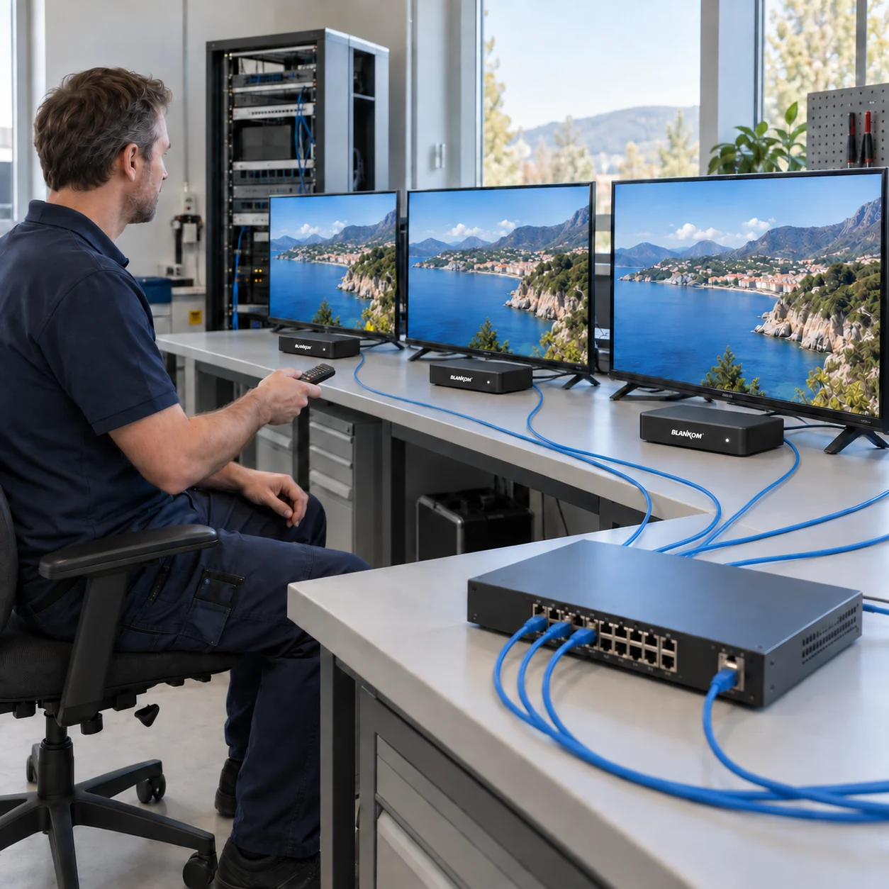
Begin with services and receivers
Before selecting a headend, list the television services, their sources and the locations where they must be available. Record the number and type of televisions, set-top boxes or software players. For every receiver family, confirm supported stream formats and how it obtains the channel list.
Decide which services must cross each part of the network. A room count alone is not enough to size an IPTV system: the source mix, stream rates, distribution method and network topology also matter. Keep any interactive portal, middleware or content-protection requirement separate from the basic live television distribution plan.
Distinguish multicast, snooping and routing
IGMP lets IPv4 receivers report interest in multicast groups. IGMPv3 can also express source-specific interest. The current specification is IGMPv3 specification, RFC 9776, which replaced RFC 3376 in 2025.
IGMP snooping observes membership traffic at the switching layer so that multicast forwarding can follow the interested ports. It is separate from routing between IP subnets. IGMP snooping considerations, RFC 4541 explains the forwarding considerations and the importance of handling membership and router ports correctly.
For each IPTV VLAN, identify the active querier function and verify that queries and receiver reports are present. Where streams must cross subnets, agree the multicast routing design with the network administrator. Do not assume that enabling a “snooping” checkbox also creates a routed multicast service.
Calculate capacity for the path, not just the headend
For an initial multicast estimate, add the rates of the distinct streams that need to traverse each link. Then account for encapsulation overhead, other traffic, rate variation and the reserve required by the network design. Check the actual forwarding behaviour during commissioning.
Illustrative calculation
If 24 streams, each measured at 8 Mbit/s at the chosen measurement point, cross one uplink, their combined rate at that point is 192 Mbit/s. This excludes overhead outside that measurement and any reserve. It is an arithmetic planning example, not a BLANKOM capacity specification.
In a multicast design, several receivers selecting the same group do not normally require a separate source stream for each receiver on their shared upstream link. The replication point and forwarding behaviour still matter. With unicast delivery, count the separate streams crossing the link. Verify the architecture used by the actual receiver or middleware rather than assuming that all television traffic is multicast.
Record the network and channel plan
| Area | Record before installation |
|---|---|
| Services | Source, service name, codec, audio, measured rate and destination group |
| Addressing | VLANs, subnets, multicast groups, ports and routing boundaries |
| Membership | Receiver IGMP support, snooping configuration and querier location |
| Links | Uplink capacity, other traffic, expected stream set and reserve |
| Receivers | Model, software version, playback format and channel-list method |
| Operations | Monitoring points, service ownership and recovery procedure |
Use an address plan agreed with the network owner. Avoid copying group addresses from an unrelated installation without checking their scope and existing use. For a network with several equipment vendors, record the relevant switch settings and expected behaviour in vendor-neutral terms as well as saving the configurations.
Verify joins, leaves and long-running playback
- Prove one service. Check a known stream on a supported receiver close to the headend.
- Verify membership. Observe the receiver joining a group and check the forwarding entry on the appropriate access switch.
- Test several locations. Select the same service on multiple receivers, then select different services and check uplink traffic.
- Leave the system running. Confirm that playback continues as membership state is refreshed. Investigate streams that stop after a repeatable interval.
- Test channel changes and recovery. Record switch time, picture and audio behaviour, and recovery after an authorised link interruption or receiver restart.
Capture the test conditions and observation point for each result. A successful laptop test at the headend does not replace an acceptance test with the installed televisions at the far end of the network.
Select the headend after the distribution plan
Once the service and network plans are clear, select equipment for the required source conversion and output. DVB reception, live HDMI or SDI encoding, transcoding and ASI/IP conversion are distinct functions. Check the relevant product’s channel count, codec and interface options instead of applying one specification to the whole portfolio.
Where an existing coaxial TV network is retained, consider the appropriate DVB-C or DVB-T distribution architecture as a separate design. The IPTV network worksheet still helps identify which parts of the signal chain need IP connectivity and which remain RF.
Practical questions
Does every television need its own multicast source stream?
Receivers can subscribe to the same multicast group. Network devices replicate the traffic where paths diverge. Confirm that the installed receiver or middleware actually uses multicast.
Is IGMP snooping the same as multicast routing?
No. Snooping concerns forwarding within the switching environment. Multicast delivery across IP subnets requires the appropriate routing design as well.
What should I provide for an IPTV headend quotation?
Send the service and source list, receiver models and count, network or coax topology, required output standards, channel-list or middleware needs and the installation scope.
Plan your IPTV distribution system
Send the service list, receiver types and network or coaxial distribution plan.
