
IPTV System Design
BLANKOM Engineering Guide Series
GUIDE 04 / 12
CAPACITY · INTERFACES · PROCESSING · EXPANSION
Select an IPTV Headend:
Capacity, Interfaces and Expansion
Select the headend only after the reception plan is known. Translate the required RF inputs, services, conditional-access needs, local sources, stream processing, IP output load and future growth into a functional equipment specification before comparing models.
01 · START FROM VERIFIED INPUTS
Headend selection begins after the service and reception plan
The source guide makes the central point directly: nobody can size or price a professional IPTV headend from a statement such as “100 channels”. The required satellite positions, transponders, services, decryption method, local sources and client-side requirements have to be known first.[1, pp. 28–30]
Guide 02 establishes the satellite/transponder/tuner basis, and Guide 03 establishes the SAT-IF path to the receiver-streamer inputs. Guide 04 uses those results to define what the headend itself must receive, process and deliver.
02 · MAP THE SIGNAL CHAIN
Separate acquisition, processing and IP output
Ralf Riedel’s system diagram separates the headend into three functional stages: acquisition, processing and IP output. The network and clients are downstream systems with their own design requirements. This separation is useful because it prevents unrelated requirements from being hidden inside one model number.[1, p. 29]
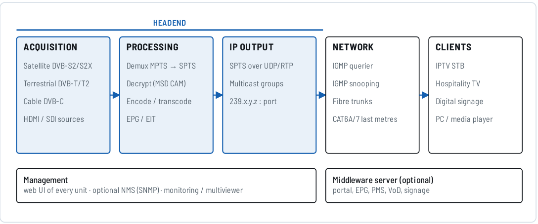
Figure 1. Headend signal path reproduced from Figure 10.2, IPTV Headend Planning Guide, 2nd edition (2026), p. 29. The diagram is architectural; current product support must be verified model by model.
ACQUISITION
What enters the headend?
Satellite, terrestrial, cable, local HDMI/SDI sources and any other verified inputs required by the project.
PROCESSING
What must happen to it?
Service selection, descrambling, encoding/transcoding, EPG/EIT handling and other verified transport-stream functions.
IP OUTPUT
What must leave the headend?
The required SPTS/MPTS outputs, destination method, total throughput and the physical data interfaces that carry them.
03 · DEFINE CAPACITY
Count every load that consumes headend resources
The headend capacity is not one number. A project may be limited by tuner inputs, service-processing capacity, CAM/descrambling resources, encoder/transcoder channels, IP output throughput, physical ports, rack space or expansion architecture. Record each load separately before comparing equipment.
| Capacity item | Project input | What to verify in the equipment |
|---|---|---|
| RF reception | Simultaneously required satellite transponders plus terrestrial/cable inputs. | Number and type of supported tuner/front-end inputs for the required standards and modulation. |
| Selected services | TV/radio services to be delivered from each received multiplex. | Service demultiplexing/output capacity under the required operating conditions. |
| Encrypted services | Services requiring authorised conditional access. | Applicable CI/CAM architecture, module count and verified service capacity. See Guide 05. |
| Local sources | HDMI/SDI or other local video sources to insert. | Required encoder interfaces, channels, formats and any licence/options. |
| Transcoding | Streams whose codec, resolution or bitrate must change. | Verified simultaneous transcoding capacity for the exact input/output profiles. |
| IP output | Number of output streams and their expected bit rates/protocols. | Aggregate throughput, port capacity and any per-port/per-stream limits. |
| Growth | Expected additional transponders, services or processing. | Spare physical slots/ports and documented expansion limits. |
04 · FREEZE THE INTERFACES
An interface matrix prevents expensive assumptions
| Boundary | Specify before selection | Typical verification question |
|---|---|---|
| RF input | DVB-S/S2/S2X, DVB-T/T2, DVB-C or other required reception standards; physical feed and tuner count. | Does the exact model/front-end support the required standard and modulation? |
| Conditional access | Provider-approved CAM/receiver method and number of encrypted services. | Are the required CI/CAM resources standard, optional or external? |
| Local baseband | HDMI, SDI or other local source interfaces and exact source formats. | Is encoding integrated or provided by a separate encoder? |
| Transport-stream I/O | Any required ASI/IP ingest, MPTS/SPTS handling or interconnection with other headend equipment. | Which interfaces exist physically and which functions are firmware/licence dependent? |
| IP data output | Ethernet port type/count, protocols, stream addressing and expected total throughput. | Can the required streams be delivered within documented aggregate and per-port limits? |
| Management | Web management, NMS/SNMP requirement, monitoring ownership and network separation. | Which management functions are included and which need an external system? |
| Power and rack | Rack units, supply type, redundancy objective, UPS context and heat/airflow constraints. | Is redundant power actually required and how is it implemented? |
The source guide presents acquisition, processing, IP output and management as separate functions. Keeping the same separation in the RFQ makes it easier to compare compact fixed-capacity devices with modular platforms without assuming that the chassis style itself guarantees a particular feature.[1, pp. 29, 45–46]
05 · SPECIFY THE PROCESSING
Make every advanced function an explicit requirement
The source guide uses EIT/EPG processing, dynamic PMT handling, PID/table manipulation, decryption, encryption, redundancy and management as examples of functions that distinguish headend platforms.[1, pp. 45–46] For procurement, list each requirement independently.
SERVICE HANDLING
Demux and signalling
Define which services must be selected and whether the project requires dynamic PMT, EIT/EPG handling, PID remapping or other PSI/SI processing. Guides 06 and 07 cover these topics in depth.
ACCESS & PROTECTION
Descrambling and encryption
Separate authorised content access from any downstream re-encryption requirement. CAM and provider conditions are project inputs, not assumed features. Guide 05 covers the conditional-access path.
MEDIA TRANSFORMATION
Encoding and transcoding
Do not specify transcoding unless a codec, resolution or bitrate conversion is actually required. Local HDMI/SDI insertion and IP-to-IP transcoding are different workloads.
06 · CHECK THE DATA PLANE
Size IP output from the stream plan, not the port label
The physical Ethernet interface is only one part of output capacity. Sum the expected bit rates of the streams that will share each headend output, include the required protocol/packetisation overhead and compare the result with the documented usable capacity of the selected equipment. Do not assume that a nominal Gigabit Ethernet connector means that every operating mode can use the complete line rate.
The source guide illustrates why the total load matters: a large headend can produce aggregate traffic above one Gigabit per second, and downstream networks require correct multicast handling.[1, pp. 47–48] Guide 08 will cover IGMP and network bandwidth in detail.
| Output group | Record | Selection consequence |
|---|---|---|
| Streams | Number of SPTS/MPTS outputs and expected average/peak bitrate where known. | Sets the aggregate processing and transport load. |
| Protocol | UDP/RTP or other required verified delivery modes. | May change packetisation, receiver compatibility or available model functions. |
| Physical ports | Required copper/SFP ports and whether traffic must be separated across them. | Determines physical connectivity and how the load can be distributed. |
| Management separation | Whether NMS/management must use a dedicated interface or VLAN. | Affects interface count, topology and security design. |
| Growth | Expected additional streams and their projected load. | Defines justified spare throughput rather than an arbitrary margin. |
07 · PLAN THE NEXT CHANGE
Expansion is physical, functional and operational
The source guide’s reference installations reserve capacity for later receiver-streamers and show that a basic linear system can be expanded with additional services. Treat that as a planning principle, not as a promise that any existing device can gain any future function.[1, pp. 65–71]
PHYSICAL HEADROOM
Rack, slots, ports and power
- Free rack space and airflow.
- Available tuner/module positions where the platform supports them.
- Spare RF/IP ports and cabling routes.
- Power and UPS capacity for the expanded configuration.
FUNCTIONAL HEADROOM
Processing and compatibility
- Verified service/stream capacity after expansion.
- Licences/options required for new functions.
- Endpoint and middleware compatibility.
- Operational monitoring and support for the larger system.
Historical architecture example—not a current bill of materials. The original figure shows a compact linear headend with receiver-streamers, local encoding and IPTV endpoints. Product names and capacities must not be reused as current specifications without verification.
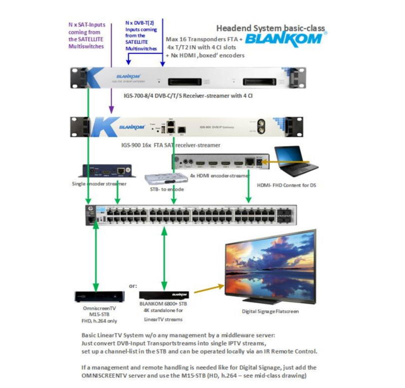
Figure 2. Historical basic linear IPTV architecture reproduced from Figure 23.4, IPTV Headend Planning Guide, 2nd edition (2026), p. 70. Current BLANKOM models and capacities must be verified separately.
08 · REVIEW BEFORE MODEL SELECTION
IPTV headend selection checklist
- The required RF tuners/front ends come from the verified reception plan.
- The selected services and encrypted services are counted separately.
- Every local HDMI/SDI or external IP source is documented.
- Required EIT, dynamic PMT, PSI/SI and PID-processing functions are explicit.
- Descrambling, re-encryption, encoding and transcoding are separate requirements.
- Aggregate IP output load and physical data interfaces are defined.
- Management/monitoring and power/redundancy expectations are documented.
- Current load and future expansion capacity are stated separately.
- Every required capability will be checked against the exact model/revision before quotation.
CUSTOMER REFERENCE
Explain why the proposed headend has this capacity and architecture
A quotation can link to the capacity, processing or expansion section so the customer can see why the proposed configuration contains a particular number of tuners, processing functions or IP interfaces. The quotation itself remains authoritative for the exact models, options and quantities.
“The proposed headend is sized from the confirmed reception inputs, selected services and required processing functions rather than from the room or TV-channel count alone. Please refer to BLANKOM Engineering Guide 04 for the capacity and interface planning method.”
09 · SEND US THE HEADEND DATA
What to include in your IPTV headend RFQ
Send the Guide 02 reception/service sheet and the Guide 03 SAT-IF distribution summary where available. Then add the required processing and output functions.
Please identify the RF inputs, selected services, encrypted services, local sources, processing requirements, output streams, data interfaces, redundancy objective and planned growth.
The enquiry opens the existing IRENIS / BLANKOM RFQ page with Guide 04 identified as the source.
Headend selection brief
IPTV HEADEND SELECTION BRIEF
Country / installation location:
Required RF standards:
Satellite transponders / other RF inputs:
Selected TV / radio services:
Encrypted services / CAM method:
Local HDMI / SDI sources:
External IP / ASI inputs if required:
EIT / dynamic PMT / PSI-SI requirements:
Encoding / transcoding requirements:
Output SPTS / MPTS count:
Expected output bitrate / protocols:
Required data ports / management ports:
Redundancy / PSU requirement:
Expansion target:
Rack / power / environmental constraints:
Project timing / open questions:
Reference: IPTV System Design — Guide 04, BLANKOM
SOURCE BASIS
Primary engineering source
This guide reformulates the headend requirements, class-selection and reference-design material in Ralf Riedel’s 2026 second edition. The capacity register, interface matrix, output worksheet, selection checklist and RFQ outline are editorial tools developed for this web series. Historical class and product examples are retained only as context and are not treated as current product specifications.
- Ralf Riedel — IPTV Headend Planning Guide, 2nd edition (2026)
Primary scope: Chapter 10, pp. 28–30; Chapter 14, pp. 45–46; Chapter 15, pp. 47–48 for output-load context; Chapter 22, pp. 65–66 and Chapter 23, pp. 67–71 for growth/reference architectures. Figure 10.2 and Figure 23.4 are reproduced as source illustrations.
Document reference: BLANKOM-EG-IPTV-04 · Web revision 1.0
IPTV System Design · BLANKOM Engineering Guide Series
- Requirements and ArchitectureGuide 01
- Services, Transponders and Tuner CountsGuide 02
- SAT-IF DistributionGuide 03
- IPTV Headend SelectionGuide 04
- Pay-TV IntegrationGuide 05
- DVB Transport Stream ValidationGuide 06
- EPG / EIT Processing and Receiver ValidationGuide 07
- IPTV Multicast Network DesignGuide 08
- IPTV Stream DeliveryGuide 09
- Local Video SourcesGuide 10
- IPTV Endpoints and ServicesGuide 11
- Resilience and OperationsGuide 12
© 2026 IRENIS GmbH. All rights reserved. Unless otherwise stated, the original text, diagrams, tables and illustrations in this publication are protected by copyright. Except where permitted by applicable law, they may not be reproduced, republished, distributed, translated, adapted or used commercially, in whole or in part, without the prior written permission of IRENIS GmbH. Any permitted quotation or reference must clearly identify IRENIS GmbH as the source and, for online use, include a link to the original publication. Third-party trademarks and credited materials remain the property of their respective owners.
