
IPTV System Design
BLANKOM Engineering Guide Series
GUIDE 03 / 12
SAT-IF · COAX · FIBRE · MULTISWITCH · MATRIX
Engineer SAT-IF Distribution:
Coax, Fibre and Multiswitches
Carry the required satellite IF paths from the dishes to the headend without turning the RF distribution into the weak link. Choose the transport medium, fan-out method, routing and installation practice from the actual distance, satellite count, headend inputs and expansion requirement.
01 · DEFINE THE RF BOUNDARY
From dish and LNB to the receiver-streamer inputs
Guide 02 establishes which satellite positions and transponders must be received. This guide covers the next engineering layer: how the corresponding SAT-IF signals are transported, distributed and routed from the LNB side to the headend inputs. The 2026 planning guide treats coax, RF-over-fibre, multiswitches and an L-band switch matrix as alternative building blocks in that path.[1, pp. 12–24]
This guide does not design the IP network after the headend and does not define system redundancy. Dish-farm backup and 1+1/N+1 strategy belong to Guide 12. Here, the objective is a stable RF input path with enough routing and fan-out for the planned receiver-streamers.
02 · CHOOSE THE TOPOLOGY
Match the distribution method to distance, fan-out and routing
| Approach | Best fit | Engineering consequence |
|---|---|---|
| Short coax runs | Dish/LNB and headend are close, with manageable loss and a limited number of paths. | Simple and economical, but attenuation and slope increase with cable length and frequency. Verify the level at the receiver input. |
| RF-over-fibre | Longer distance, several buildings, difficult EMC environment or large fan-out. | Moves SAT-IF over single-mode fibre; requires the correct optical architecture, optical power budget and electrical conversion at the destination. |
| Headend multiswitch | Several receiver-streamer tuners need access to fixed satellite positions/polarisations. | Provides fan-out and receiver selection. Cascade outputs, levels and termination must be engineered correctly. |
| L-band matrix | Inputs must be routed flexibly to selected headend receivers or downstream distribution. | Adds remote routing flexibility. It does not replace the need to verify RF levels, LNB supply, cabling and downstream fan-out. |
The source guide illustrates all four approaches. Treat its distance values and product examples as planning examples, not as universal limits for every cable, optical budget or hardware revision. Final lengths, loss and levels must be checked for the selected components and site.

Figure 1. Satellite reception concepts reproduced from IPTV Headend Planning Guide, 2nd edition (2026), Figure 23.1, p. 67. Product labels are historical examples; use current documentation for a new project.
03 · USE COAX WHERE IT FITS
Understand attenuation, slope and the real cable length
Satellite IF is an RF signal. Coax attenuates it, and the loss increases with frequency. A long run therefore arrives with a slope: the upper part of the 950–2150 MHz band is weaker than the lower part. Amplification can restore level, but it also adds noise and cannot recover quality that has already been lost.[1, pp. 12–14]
The source guide uses “below about 50 m” as a practical example for short coax runs. Do not turn that number into a universal design rule. The permitted length depends on cable type, frequency, connectors, splitters, input level, required margin and the receiver specification. Calculate or measure the actual path.

Figure 2. Cable-slope principle reproduced from IPTV Headend Planning Guide, 2nd edition (2026), Figure 5.1, p. 12. Illustration not to scale.
COAX IS ATTRACTIVE WHEN
The RF path is short and controlled
Few metres, known cable, limited splitting and easy access to the headend can make coax the simplest solution.
CHANGE THE ARCHITECTURE WHEN
Distance and fan-out dominate
If loss, slope, multiple buildings or the number of parallel SAT-IF paths make the copper plant complex, evaluate optical transport instead of repeatedly correcting a weak RF path.
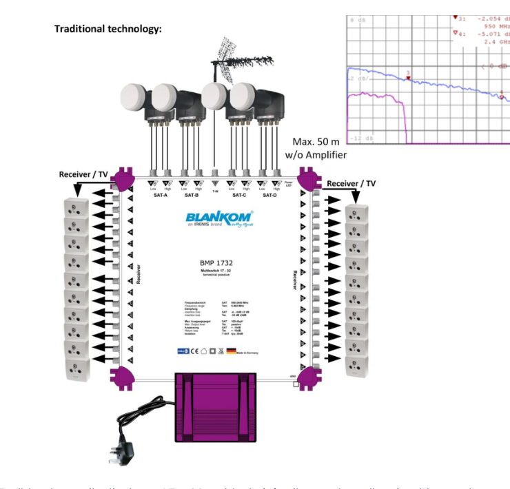
Figure 3. Traditional coax distribution example reproduced from Figure 5.2, p. 13. The equipment image is historical; the engineering point is the complete SAT-IF fan-out and the cumulative effect of distance.
04 · CLOSE THE UNUSED RF PATHS
Terminate unused cascade outputs correctly
The planning guide gives one practical rule repeatedly: unused cascade/trunk outputs of the multiswitch should be closed with 75 Ω terminators that include a DC block. An open RF output can reflect signal back into the system; a terminator without the required DC isolation can short the LNB supply carried on that path.[1, pp. 13, 15–16]
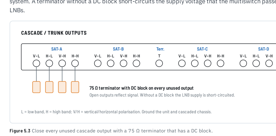
Figure 4. Trunk-termination principle reproduced from Figure 5.3, p. 13.
05 · MOVE SAT-IF OVER DISTANCE
Use RF-over-fibre when copper becomes the constraint
The source guide describes several optical architectures: combining multiple SAT-IF paths onto one single-mode fibre using CWDM, using separate single-mode fibres for satellite positions, and optically splitting one satellite position to several buildings. The common engineering purpose is to transport the RF band over distance without the loss and electromagnetic-interference behaviour of a long coax plant.[1, pp. 15–19]
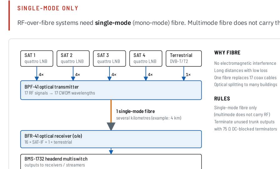
Figure 5. Four satellite positions plus terrestrial RF on one fibre, reproduced from Figure 6.1, p. 15. The BPF-41/BFR-41 labels are product examples in the source architecture.
| Variant | What it does | Design check |
|---|---|---|
| Many RF paths on one fibre | CWDM combines the polarisation/band paths from several satellites and terrestrial RF. | Verify the exact transmitter/receiver pair, optical power, fibre type and supported RF inputs. |
| One fibre per satellite position | Keeps the satellite positions optically separate and converts them back to electrical SAT-IF near the headend. | Verify the number of fibres, receiver power arrangement and the required multiswitch inputs. |
| Optical splitting to several destinations | Shares one optical SAT-IF source with several buildings or sub-headends. | Calculate splitter loss and optical budget for the selected transmitter, fibre lengths and number of outputs. |
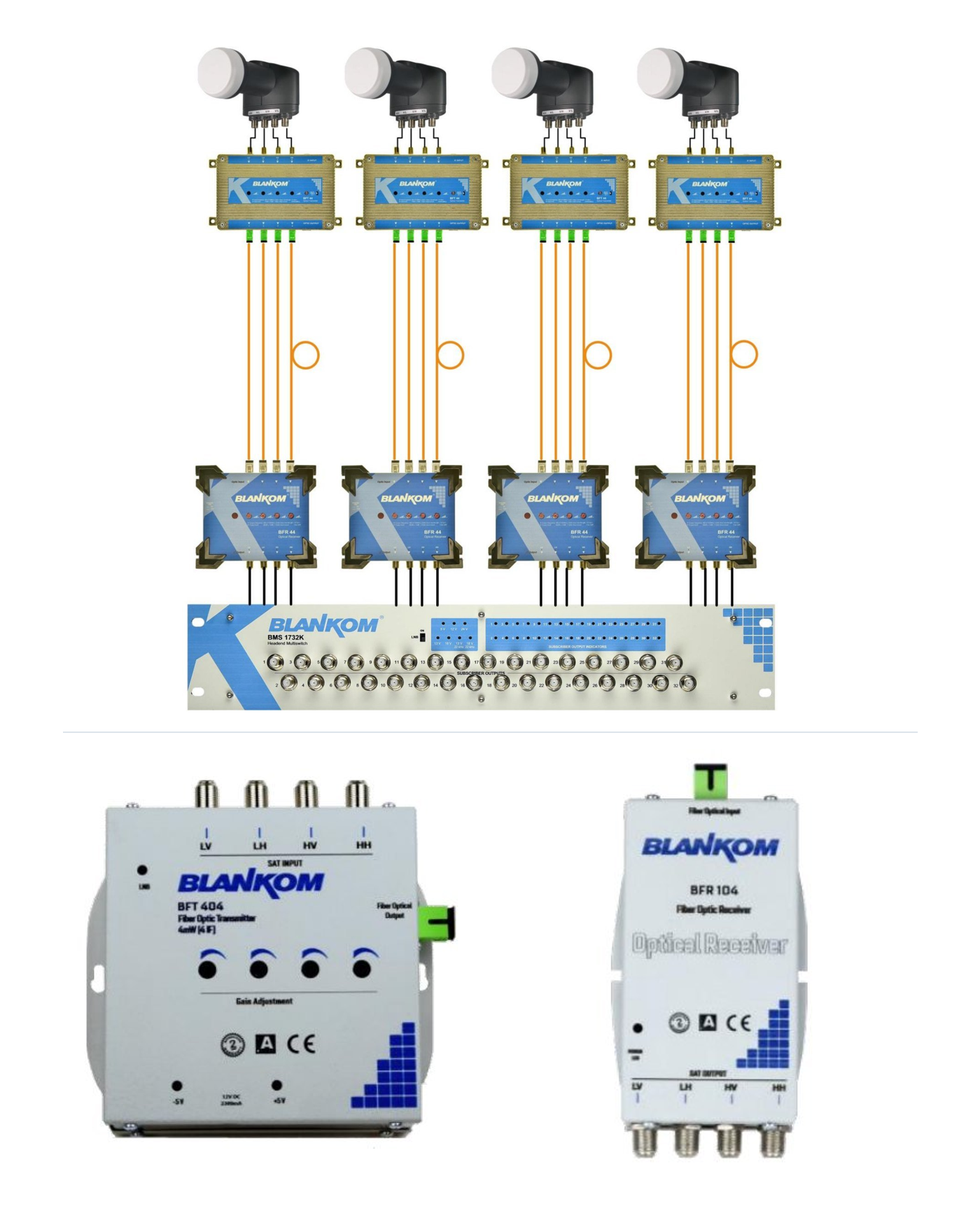
Figure 6. One-fibre-per-satellite-position concept and compact optical hardware examples reproduced from Figures 6.3–6.5, p. 17. The source explicitly notes earlier model labels.
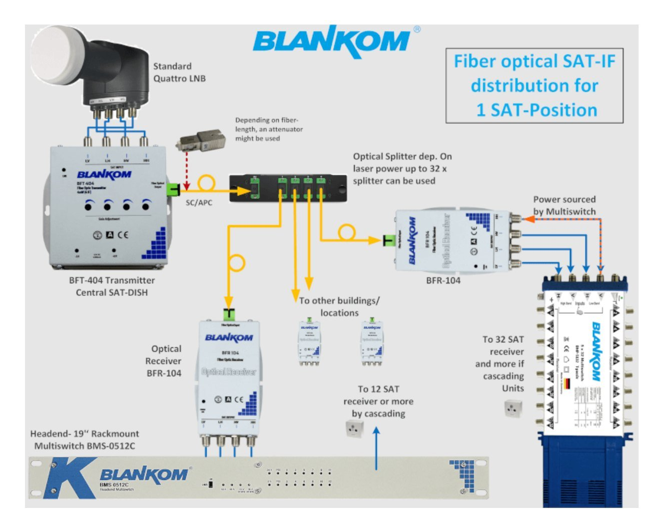
Figure 7. Optical splitting to multiple buildings reproduced from Figure 6.6, p. 18. Historical product names are retained as part of the source illustration.
06 · FAN OUT OR ROUTE THE RF
Use a multiswitch for distribution; use a matrix for flexible routing
A headend multiswitch distributes the available SAT-IF inputs to multiple receiver/tuner outputs. A switch matrix addresses a different requirement: it allows selected RF inputs to be routed to selected outputs and changed remotely. The source guide uses the BLANKOM BMM-1716 as a 17-input/16-output example of this routing concept.[1, pp. 20–21]
MULTISWITCH
Fixed fan-out to many tuners
Use when several receiver-streamer tuners need access to the installed satellite positions. Check the input count, receiver outputs, cascade path, level plan and future expansion.
L-BAND MATRIX
Route selected inputs to selected outputs
Use when headend input assignment must be changed or controlled remotely. A matrix can feed receivers directly or feed a downstream passive/active distribution stage.
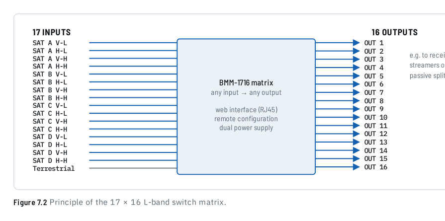
Figure 8. L-band switch-matrix principle reproduced from Figure 7.2, p. 21.
07 · INSTALL FOR REPEATABLE RF PERFORMANCE
Cables, connectors, bend radius, grounding and measurement
The 2026 guide emphasises that the headend can only be as good as the signal it receives. Dish alignment, LNB output quality, cable handling and connectors are therefore part of the headend design—not merely installation details. It recommends professional crimp/self-install or compression F connectors matched to the cable diameter and rejects screw-on F connectors for this professional use.[1, pp. 23–24]
For bend radius, follow the cable manufacturer’s specification. The source guide gives 5 cm as a general minimum example for the coax it discusses; it should not override a product-specific cable requirement.
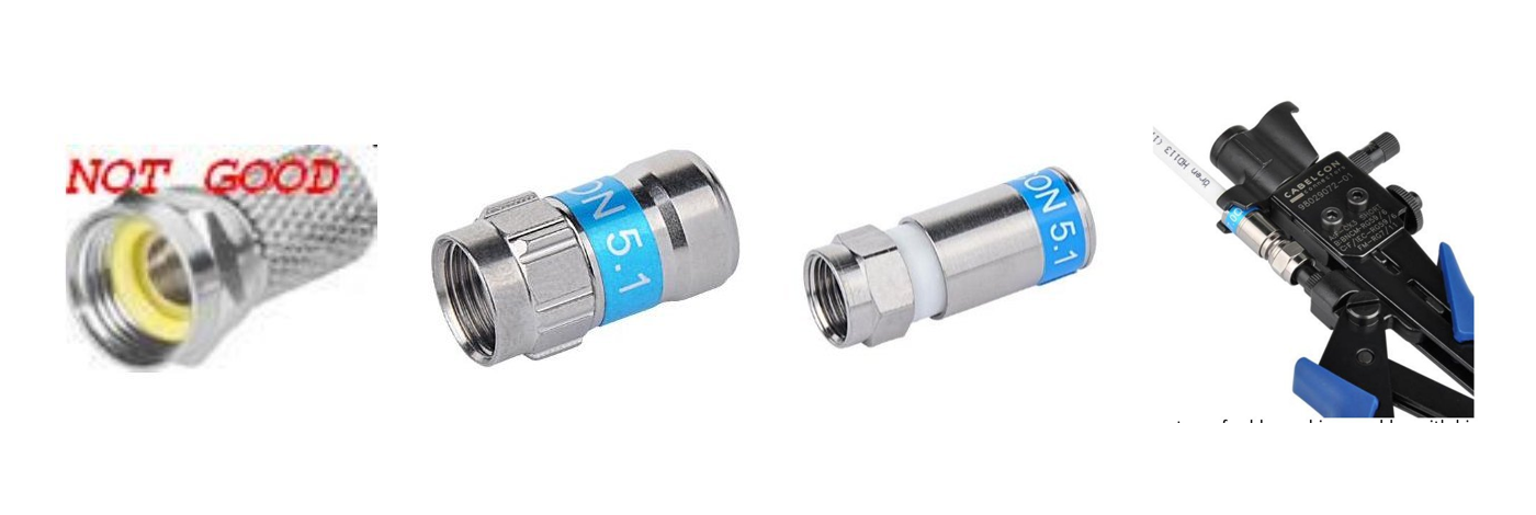
Figure 9. Connector examples reproduced from Figures 8.1–8.4, p. 23.
Installation review before connecting the receiver-streamers
- Satellite positions, LNB type and all required SAT-IF paths are documented.
- Coax lengths, cable types, connector types and intermediate splitters/couplers are recorded.
- Optical paths identify fibre type, transmitter/receiver pair, splitters and optical budget.
- Every multiswitch/matrix input and output has a defined destination.
- Unused cascade/trunk outputs are correctly terminated.
- Grounding and bonding follow the applicable installation rules for the site.
- Dish/LNB alignment and RF level/quality are checked at defined measuring points.
- The final receiver-streamer inputs are within the verified input conditions of the selected equipment.
CUSTOMER REFERENCE
Explain why the proposed RF distribution is part of the system design
A quotation can link to the coax, fibre or routing section to explain why the proposed multiswitch, matrix or optical transport is required. The quotation itself should still state the selected models, quantities, accessories, optical splitters/attenuators where applicable, cable scope and installation responsibility.
“The proposed SAT-IF distribution is based on the confirmed satellite positions, distance to the headend and number of receiver inputs. Please refer to BLANKOM Engineering Guide 03 for the distinction between short coax distribution, RF-over-fibre transport and headend fan-out/routing.”
08 · SEND US THE RF DISTRIBUTION DATA
What to include in your SAT-IF distribution RFQ
Send the satellite/reception schedule from Guide 02 together with the physical path from the dishes to the headend. If the building route is not final, send the known distances and mark the open points.
Please include the satellite positions, LNB outputs, distance to the headend, available coax/fibre, required tuner inputs, fan-out/cascade needs and existing RF equipment.
The enquiry opens the existing IRENIS / BLANKOM RFQ page with Guide 03 identified as the source.
RF distribution brief outline
SAT-IF DISTRIBUTION BRIEF
Country / installation location:
Satellite positions:
LNB type / outputs:
Dish-to-headend distance:
Existing coax routes / cable types:
Available single-mode fibre routes:
Number of receiver-streamer tuner inputs:
Multiswitch / matrix / splitter requirement:
Cascade or sub-headend locations:
Existing RF-over-fibre equipment:
Termination / grounding constraints:
Redundancy requirement (if any):
Project timing / open questions:
Reference: IPTV System Design — Guide 03, BLANKOM
SOURCE BASIS
Primary engineering source
This guide reformulates the SAT-IF distribution, fibre, matrix and installation material in Ralf Riedel’s 2026 second edition. Comparison tables, the RFQ outline and the quotation-reference wording are editorial tools developed for this web series. Distances and historical product labels from the source are retained as examples and are not treated as current universal specifications.
- Ralf Riedel — IPTV Headend Planning Guide, 2nd edition (2026)
Primary scope: Chapter 5, pp. 12–14; Chapter 6, pp. 15–19; Chapter 7 matrix section, pp. 20–21; Chapter 8, pp. 23–24; reference topology Figure 23.1, p. 67. Dish-farm redundancy from Chapter 7 is reserved for Guide 12.
Document reference: BLANKOM-EG-IPTV-03 · Web revision 1.0
IPTV System Design · BLANKOM Engineering Guide Series
- Requirements and ArchitectureGuide 01
- Services, Transponders and Tuner CountsGuide 02
- SAT-IF DistributionGuide 03
- IPTV Headend SelectionGuide 04
- Pay-TV IntegrationGuide 05
- DVB Transport Stream ValidationGuide 06
- EPG / EIT Processing and Receiver ValidationGuide 07
- IPTV Multicast Network DesignGuide 08
- IPTV Stream DeliveryGuide 09
- Local Video SourcesGuide 10
- IPTV Endpoints and ServicesGuide 11
- Resilience and OperationsGuide 12
© 2026 IRENIS GmbH. All rights reserved. Unless otherwise stated, the original text, diagrams, tables and illustrations in this publication are protected by copyright. Except where permitted by applicable law, they may not be reproduced, republished, distributed, translated, adapted or used commercially, in whole or in part, without the prior written permission of IRENIS GmbH. Any permitted quotation or reference must clearly identify IRENIS GmbH as the source and, for online use, include a link to the original publication. Third-party trademarks and credited materials remain the property of their respective owners.
