
IPTV System Design
BLANKOM Engineering Guide Series
GUIDE 02 / 12
SATELLITES · TRANSPONDERS · SERVICES · TUNER COUNT
Plan Satellite Reception:
Services, Transponders and Tuner Counts
Do not size an IPTV headend from the number of TV services alone. First identify the wanted services, group them by satellite and transponder, verify reception at the site and then count the transponders that must be received simultaneously.
01 · DEFINE THE RECEPTION TASK
What this guide calculates—and what it does not
This guide starts after the project has identified which television and radio services are actually required. Its task is to translate that list into satellite positions, transponders and reception inputs. The 2026 planning guide makes the same distinction: a TV service belongs to a transport stream carried on one RF transponder, and the complete transponder has to be received before selected services can be demultiplexed for IPTV.[1, pp. 29–31]
This guide does not select a particular BLANKOM model, calculate the detailed SAT-IF distribution, design redundancy, or specify conditional-access equipment. Those tasks belong to later guides in the series.
02 · BUILD THE RECEPTION DATA
Five steps from wanted services to headend inputs
Ralf Riedel’s second edition reduces the reception survey to five practical steps: choose the satellites, collect the transponder data, identify the services, determine the reception requirements and prepare one documented service sheet. That sequence should be completed before equipment selection.[1, pp. 31–35]
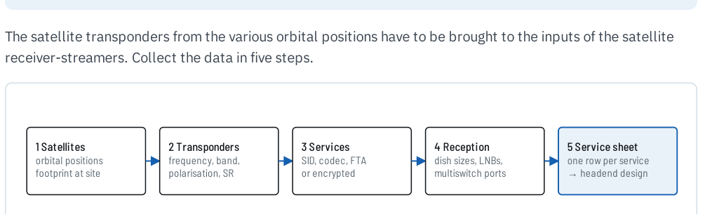
Figure 1. Five-step planning workflow reproduced from IPTV Headend Planning Guide, 2nd edition (2026), Figure 11.1, p. 31.
INPUT
Wanted services
What the customer actually wants to watch or hear, including languages and encrypted/FTA status.
ENGINEERING
Satellite + transponder map
Where those services are carried and which RF carriers must be received simultaneously.
OUTPUT
Reception schedule
A service sheet that can support dish, multiswitch/matrix and headend planning.
03 · LOCATE THE SERVICES
Start with satellite position and reception footprint
The first engineering question is not “How many channels?” but “On which satellites are the required services carried?” Record the orbital position of every satellite that contributes at least one required service. Then check the reception footprint at the actual installation site, because the beam coverage and level influence dish selection.[1, pp. 30–34]
RECORD
Satellite position
- Orbital position.
- Required services carried there.
- Reception footprint at the project site.
- Any uncertainty that requires site verification.
DO NOT ASSUME
Dish size from a service name
The service name alone does not define the required dish. Use the footprint and the actual project location. Final dish sizing and margin should be verified as part of the reception design.
04 · GROUP BY RF CARRIER
Collect the transponder data for every required service
For each required service, identify the transponder that carries it. The planning guide specifically calls for frequency, polarisation, symbol rate, FEC, modulation and the services carried. For SAT-IF planning, also record the relevant band/polarisation relationship used by the receiving installation.[1, pp. 30–33]
| Field | Why it matters | Status |
|---|---|---|
| Satellite / orbital position | Associates the RF carrier with the correct dish/LNB and reception path. | Required |
| Frequency | Identifies the RF transponder to tune. | Required |
| Polarisation and band | Determines the SAT-IF path in a conventional quattro-LNB/multiswitch system. | Required |
| Symbol rate / FEC / modulation | Defines the demodulation parameters and may affect receiver capability. | Required |
| Service list on that transponder | Shows how many wanted services share one tuner input. | Required |
05 · BUILD THE SERVICE LIST
Keep one row per service, but group by transponder
The planning guide recommends a service sheet with one row per service. That structure keeps language, encryption status, service ID, codec and project remarks attached to the viewer-facing service while still allowing the rows to be grouped by transponder.[1, pp. 31–35]
For quotation work, add a simple priority field such as required, optional or to be confirmed. That lets the engineer distinguish the base configuration from later additions without hiding open points.
Useful columns in the service sheet
- Service name and language.
- Satellite and orbital position.
- Transponder frequency, polarisation, symbol rate, FEC and modulation.
- FTA or encrypted status.
- Service ID where available.
- Video/audio codec information where relevant to downstream compatibility.
- Required / optional / to be confirmed.
- Project remarks and source of the data.
06 · DERIVE THE STARTING CAPACITY
From transponder count to starting tuner count
For a conventional DVB-S/S2/S2X receiver-streamer, one tuner is tuned to one RF transponder at a time. The practical starting point is therefore the number of distinct transponders that must be received simultaneously, not the number of selected TV services. Verify the final count against the architecture and limits of the selected headend platform.
| Satellite | Wanted services | Distinct transponders used | Starting tuner inputs |
|---|---|---|---|
| Satellite A | 10 | 4 | 4 |
| Satellite B | 8 | 3 | 3 |
| Total | 18 services | 7 transponders | 7 |
The example assumes all seven transponders must be available at the same time and does not include redundancy, spare capacity or model-specific restrictions.
07 · DOCUMENT BEFORE YOU BUY
The service sheet becomes the engineering baseline
The source guide explicitly recommends documenting the installation from the planning stage. A service sheet is more than a purchasing list: it becomes the reference used to check the reception design, configure the headend, explain the quotation and later maintain the installation.[1, pp. 34–35]
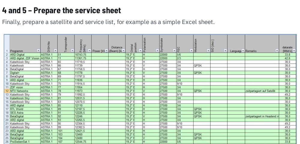
Figure 2. Example service sheet reproduced from IPTV Headend Planning Guide, 2nd edition (2026), Figure 11.6, p. 34. The historical spreadsheet is an example of structure, not current reception data.
08 · REVIEW BEFORE MODEL SELECTION
Reception-planning checklist
- Every required service has a named source.
- Every satellite service is assigned to an orbital position and transponder.
- Frequency, polarisation, symbol rate, FEC and modulation are recorded.
- Satellite footprint and project location have been checked.
- FTA and encrypted services are separated.
- Distinct simultaneously required transponders have been counted.
- Spare capacity and redundancy are listed separately from the base tuner count.
- The service sheet identifies its data source and open questions.
09 · SEND US THE RECEPTION DATA
What to include in your satellite IPTV RFQ
The fastest route to a meaningful headend proposal is a service sheet or equivalent list. If some reception data is still missing, send the known information and mark the rest “to be confirmed”.
Please include the installation location, satellite positions, required services, transponder data, encrypted-content status and expected future additions.
The enquiry opens the existing IRENIS / BLANKOM RFQ page with Guide 02 identified as the source.
Reception brief outline
SATELLITE IPTV RECEPTION BRIEF
Country / installation location:
Required TV and radio services:
Required languages:
Satellite positions:
Transponders / frequencies:
Polarisation / band:
Symbol rate / FEC / modulation:
FTA or encrypted services:
Existing dishes / LNBs / multiswitches:
Future services or satellite positions:
Redundancy requirement:
Project timing / open questions:
Reference: IPTV System Design — Guide 02, BLANKOM
SOURCE BASIS
Primary engineering source
This guide reformulates the reception-planning method in Ralf Riedel’s 2026 second edition. The worked tuner-count example, RFQ structure and project-status fields are editorial tools added for the web series. They are not product specifications.
- Ralf Riedel — IPTV Headend Planning Guide, 2nd edition (2026)
Primary scope: Chapter 10, pp. 29–30; Chapter 11, pp. 31–35. Figure 11.1 provides the five-step survey workflow; Figure 11.6 shows the service-sheet structure.
Document reference: BLANKOM-EG-IPTV-02 · Web revision 1.0
IPTV System Design · BLANKOM Engineering Guide Series
- Requirements and ArchitectureGuide 01
- Services, Transponders and Tuner CountsGuide 02
- SAT-IF DistributionGuide 03
- IPTV Headend SelectionGuide 04
- Pay-TV IntegrationGuide 05
- DVB Transport Stream ValidationGuide 06
- EPG / EIT Processing and Receiver ValidationGuide 07
- IPTV Multicast Network DesignGuide 08
- IPTV Stream DeliveryGuide 09
- Local Video SourcesGuide 10
- IPTV Endpoints and ServicesGuide 11
- Resilience and OperationsGuide 12
© 2026 IRENIS GmbH. All rights reserved. Unless otherwise stated, the original text, diagrams, tables and illustrations in this publication are protected by copyright. Except where permitted by applicable law, they may not be reproduced, republished, distributed, translated, adapted or used commercially, in whole or in part, without the prior written permission of IRENIS GmbH. Any permitted quotation or reference must clearly identify IRENIS GmbH as the source and, for online use, include a link to the original publication. Third-party trademarks and credited materials remain the property of their respective owners.
