
IPTV System Design
BLANKOM Engineering Guide Series
GUIDE 08 / 12
MULTICAST · BANDWIDTH · IGMP QUERIER · SNOOPING · SWITCHING
Design an IPTV Multicast Network:
Bandwidth, IGMP and Switching
A multicast IPTV network works only when the switches forward each stream where it is actually requested. Calculate the aggregate stream load, provide enough backbone capacity, place one IGMP querier and use snooping at the access switches so endpoint ports are not flooded with every channel.
01 · CHOOSE THE DISTRIBUTION MODEL
Multicast changes where the bandwidth is consumed
In the planning guide, multicast is the preferred model when many IPTV clients are active at the same time. The headend sends one copy of each service; the network switches replicate that stream only toward ports that have joined the multicast group. Unicast instead creates an individual stream per receiving client.[1, pp. 3–4, 47]
This guide concentrates on the managed local multicast network. It does not replace a complete IT-network design, and it does not define the multicast-address or UDP/RTP port plan in detail; those topics continue in Guide 09.
MULTICAST
One source stream, replicated by the network
Useful when many TVs or STBs may watch at the same time. The switching infrastructure must understand group membership and restrict each stream to the joined ports.
UNICAST
One session or stream per client
Can suit smaller numbers of simultaneously active clients, but server-side load and link bandwidth grow with the number of viewers.
02 · CALCULATE THE TRAFFIC
Dimension the headend uplink from the actual service bit rates
The planning guide uses an example of 200 streams averaging 6–8 Mbit/s, or roughly 1.4 Gbit/s in total, to show why the network core may carry far more traffic than a single endpoint port can accept. It also notes that many TVs and STBs still use 100BASE-T ports.[1, p. 48]
Treat those values as an example, not as a universal design limit. For a real project, sum the verified bit rates of the services that leave each headend interface, then check every uplink and trunk that can carry that aggregate traffic. Allow the project designer to define the required engineering margin rather than applying an arbitrary percentage.
| Network point | What to calculate | Design question |
|---|---|---|
| Headend output | Sum of all streams assigned to that physical output | Can the interface carry the configured service set without operating at an unacceptable load? |
| Core / distribution trunk | Maximum aggregate traffic that can traverse the trunk | Does the link carry one headend output, several outputs or additional data traffic? |
| Access switch | Traffic required by the joined groups on each downstream branch | Are the uplink and switching fabric sized for the services that can be requested? |
| Endpoint port | Normally the streams actually joined by that endpoint | Does IGMP snooping prevent unrelated multicast streams from reaching the port? |
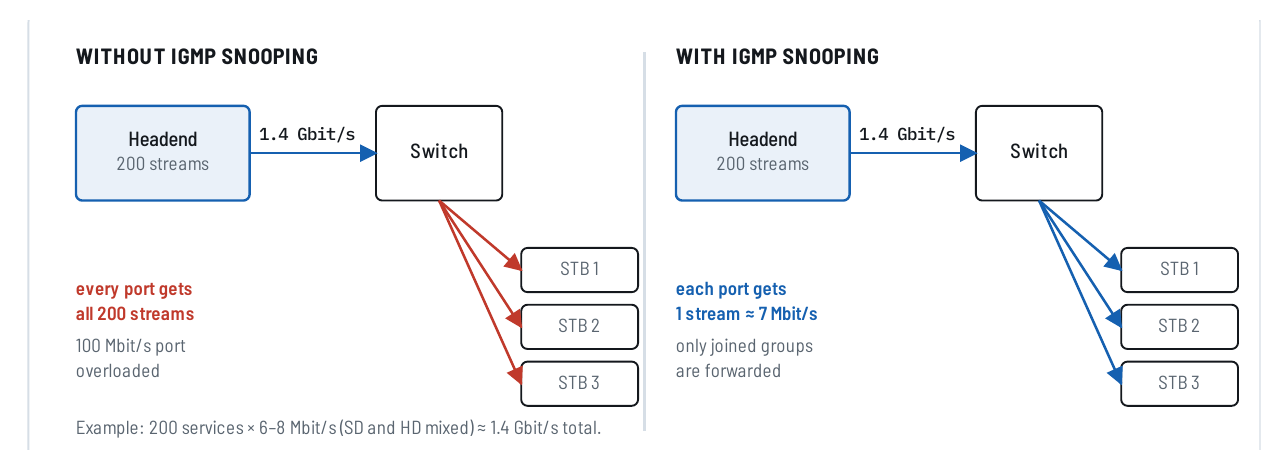
Figure 1. Source example: without snooping every access port receives the full multicast set; with snooping only joined groups are forwarded. Reproduced from IPTV Headend Planning Guide, 2nd edition (2026), Figure 15.1, p. 48.
03 · CONTROL GROUP MEMBERSHIP
One querier, snooping switches and explicit client membership
The planning guide separates two network functions. The IGMP querier periodically asks which multicast groups still have members. The snooping switches listen to the query/report/leave exchange and build port-level forwarding information, so a stream is sent only where it has been requested.[1, pp. 49–51]
CLIENT
Join / report / leave
The TV, STB or other host requests a multicast group and later reports continued membership or leaves it.
SNOOPING SWITCH
Learn the receiving port
The switch observes IGMP exchanges and forwards the multicast group only to ports that need it.
QUERIER
Maintain the membership state
A Layer 3 switch or router can act as the querier and send periodic membership queries.
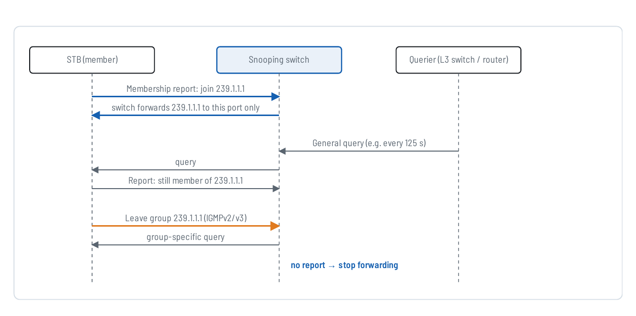
Figure 2. IGMP join, periodic query, membership report and leave sequence, reproduced from IPTV Headend Planning Guide, 2nd edition (2026), Figure 16.1, p. 50.
04 · SIZE THE SWITCHING HIERARCHY
Keep the heavy aggregate traffic in the backbone
The planning guide recommends fibre from the headend switch to floor switches in new buildings or major renovations, with copper used for the final room connection. Its Figure 8.7 illustrates a headend switch feeding several floor switches over optical trunks.[1, p. 24]
The network engineer still has to determine the actual link speeds, switch capacities, VLAN design, redundancy and physical topology for the project. The source drawing is an architecture example—not a current bill of materials.
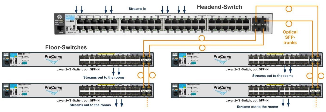
Figure 3. Headend-to-floor Ethernet/IP fibre-backbone example reproduced from IPTV Headend Planning Guide, 2nd edition (2026), Figure 8.7, p. 24. Switch models are historical examples.
BACKBONE
Carry the aggregate traffic
Dimension core and floor-switch uplinks from the maximum traffic that can traverse each path, not from the speed of an individual TV port.
EDGE
Deliver only joined streams
Access ports should receive the multicast groups their endpoint has requested, plus the other traffic intentionally assigned to that port.
05 · OBSERVE REAL CLIENT BEHAVIOUR
Validate joins and leaves with the actual TVs and STBs
The source guide shows a DVB/IP gateway feeding many multicast groups into an IGMP-aware switch while different clients join and leave individual groups. This is the behaviour to verify during commissioning: changing a channel should cause the network to stop forwarding the old group and begin forwarding the newly requested group to that endpoint.[1, p. 50]
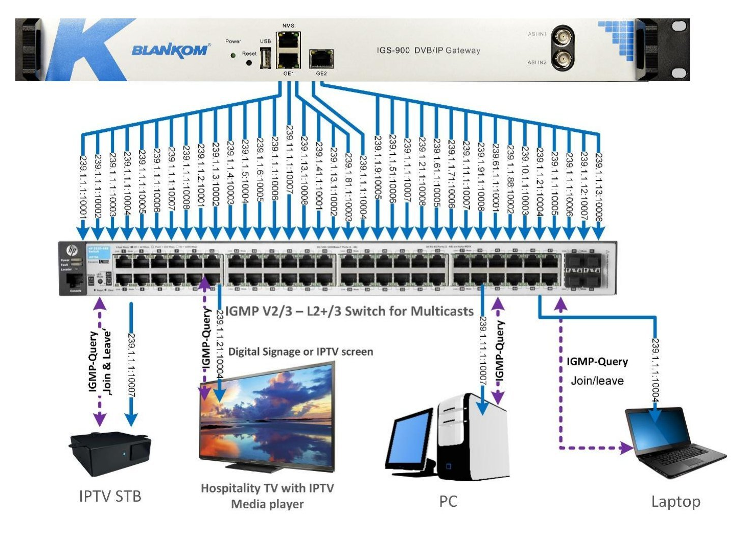
Figure 4. Example multicast network with clients joining and leaving groups, reproduced from IPTV Headend Planning Guide, 2nd edition (2026), Figure 16.2, p. 50. Equipment shown is an illustrative source example.
06 · COMMISSION THE NETWORK
Prove the forwarding behaviour before handover
The checklist below converts the planning-guide concepts into a practical acceptance sequence. It is an editorial commissioning tool for this web series, not a manufacturer-specific switch procedure.
-
Confirm the stream inventory
Record the services, measured or verified design bit rates and the physical headend output carrying each stream.
-
Confirm the querier
Identify the intended Layer 3 switch or router acting as IGMP querier in the IPTV multicast domain. Check that an unintended second querier is not changing the design behaviour.
-
Confirm snooping
Check that the access/distribution switches learn multicast membership and do not flood the complete service set to an idle endpoint port.
-
Test channel changes
Use the actual TV or STB. Join several groups in sequence and confirm that the forwarding state follows the selected service.
-
Check trunk utilisation
Observe the headend and backbone interfaces under the intended service load and compare the traffic with the documented design calculation.
-
Document the handover state
Record switch/VLAN roles, querier location, software/firmware versions, active multicast features and any project-specific limits or exceptions.
CUSTOMER REFERENCE
Explain the network assumptions behind the proposed headend
A quotation can reference this guide when the headend is proposed for a managed multicast LAN. The quotation should still state the actual headend interfaces and project scope; this guide does not make the customer’s switching infrastructure part of the BLANKOM supply unless explicitly quoted.
“The proposed headend is intended for a managed multicast IPTV network. Please refer to BLANKOM Engineering Guide 08 for the bandwidth, IGMP querier/snooping and commissioning assumptions that apply to the customer-provided Ethernet distribution network.”
07 · DEFINE THE NETWORK INTERFACE
What to include in your multicast-network RFQ
Tell us how many services leave the headend, their bit rates, the available switch/uplink capacities and who is responsible for configuring the Ethernet network.
The most useful request identifies headend stream count, total bit rate, physical output ports, backbone topology, endpoint port speeds, VLANs, IGMP querier location, snooping support and the local network integrator’s scope.
The request opens the existing IRENIS / BLANKOM enquiry page. The local switching configuration remains project-specific unless explicitly included in our quotation.
Project brief outline
IPTV MULTICAST NETWORK PROJECT BRIEF
Country / installation location:
Number of IPTV endpoints:
Endpoint types: TV / STB / PC / other
Endpoint Ethernet speed(s):

Number of multicast services:
Measured / design bit rate per service:
Total headend output bit rate:
Number and speed of headend output ports:

Core / distribution topology:
Backbone link speeds:
Fibre trunks to floors: yes / no / unknown
VLAN(s) used for IPTV:

IGMP version supported by switches:
IGMP snooping enabled: yes / no / unknown
Intended IGMP querier device / location:
Existing switch make / model / software:

Who supplies/configures the network:
Required commissioning / acceptance test:
Existing infrastructure to retain:
Quantity / timing / open questions:
Reference: IPTV System Design - Guide 08, BLANKOM
ENGINEERING FAQ
Questions that matter in multicast-network design
Why is multicast useful for a hotel or hospital with many TVs?
The headend sends one copy of each channel into the network. The switches replicate a stream only toward clients that have joined its multicast group, so the headend load does not grow with every viewer of the same service.
Why do we need IGMP snooping?
Without snooping, a switch may flood multicast traffic to ports that did not request it. Snooping uses IGMP membership information to restrict each group to the relevant ports.
What does the IGMP querier do?
It sends membership queries and maintains the group-membership process. In the planning guide, a Layer 3 switch or router is the intended querier.
Is a 1 Gbit/s headend port enough?
Not necessarily. Add the actual bit rates of the streams assigned to that port and compare the result with the interface and downstream-link capacities. The source guide’s 200-stream / 1.4-Gbit/s case is an example, not a universal design value.
Do you supply the Ethernet switches?
Usually not. The planning guide states that local system integrators normally provide the network equipment. The project quotation should define responsibilities explicitly.
Where do multicast addresses and UDP/RTP ports fit?
They are part of the stream-delivery plan and continue in Guide 09. Guide 08 focuses on bandwidth and switch behaviour.
SOURCE BASIS
Primary engineering source
This guide reformulates the multicast-network sections of Ralf Riedel’s published 2026 second edition. The link-capacity worksheet, commissioning sequence, RFQ structure and quotation-reference wording are editorial engineering tools added for the web series; they are not switch-manufacturer specifications.
- Ralf Riedel — IPTV Headend Planning Guide, 2nd edition (2026)
Primary scope: Chapter 1, pp. 3–5 for multicast/unicast basics; Chapter 8, p. 24 for the Ethernet/fibre backbone; Chapter 15, pp. 47–48 for multicast bandwidth and the IGMP-snooping example; Chapter 16, pp. 49–51 for the querier/snooping process and network behaviour without IGMP.
Document reference: BLANKOM-EG-IPTV-08 · Web revision 1.0
IPTV System Design · BLANKOM Engineering Guide Series
- Requirements and ArchitectureGuide 01
- Services, Transponders and Tuner CountsGuide 02
- SAT-IF DistributionGuide 03
- IPTV Headend SelectionGuide 04
- Pay-TV IntegrationGuide 05
- DVB Transport Stream ValidationGuide 06
- EPG / EIT Processing and Receiver ValidationGuide 07
- IPTV Multicast Network DesignGuide 08
- IPTV Stream DeliveryGuide 09
- Local Video SourcesGuide 10
- IPTV Endpoints and ServicesGuide 11
- Resilience and OperationsGuide 12
© 2022–2026 BLANKOM, IRENIS GmbH. All rights reserved. Technical details, product names and compatibility are subject to change. Verify current product documentation and project-specific requirements before specification or purchase.
