
IPTV System Design
BLANKOM Engineering Guide Series
GUIDE 12 / 12
REDUNDANCY · MONITORING · OPERATIONS · HANDOVER
Plan IPTV Resilience and Operations:
Redundancy, Monitoring and Handover
Decide which failures are worth protecting against, how quickly service must recover, how faults will be noticed and who will act. A resilient IPTV system is not just duplicated hardware; it is a documented operating plan.
01 · DEFINE WHAT CAN BE PROTECTED
Start with failure scope, not with duplicated equipment
The source guide makes the limit explicit: no TV system is 100% redundant. The complete content chain begins at the broadcaster, passes through the uplink and satellite, and reaches the receiving site. The local design can only protect the parts of the chain under project control.[1, pp. 8–9]
Before specifying standby hardware, classify the services and failure domains. A major sports channel may justify a different protection level from a rarely watched service; a dish-farm path may require a different response from an encoder or network-switch failure.
| Failure domain | Project can influence | Typical planning question |
|---|---|---|
| Upstream broadcaster / satellite | Usually no | What happens when the source itself is unavailable? |
| Dish / LNB / SAT-IF path | Yes, from the receiving site onwards | Which satellite positions deserve master/backup reception? |
| Receiver / streamer / processing | Yes | N+1 shared spare or mirrored 1+1? |
| IP network | Yes, with the local integrator | Where are the switch, uplink and power single points of failure? |
| Endpoint / room | Partly | Is a failed TV/STB a local service issue or part of the resilience requirement? |
02 · CHOOSE THE SWITCH-OVER MODEL
N+1 shares a spare; 1+1 mirrors the active path
In the source guide, N+1 uses one standby unit to protect several active units. External control must load the failed unit’s configuration into the spare, so service is interrupted during fail-over and again during restoration. A 1+1 design pairs every active unit with a mirror and swaps the input/output path automatically; the source describes the interruption as practically unnoticeable, but the cost is duplicated hardware.[1, pp. 8–9]
Only one unit may transmit a given multicast group at a time. Two simultaneous senders using the same stream address are not redundancy; they are a network conflict.
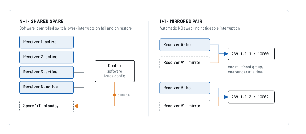
Figure 1. N+1 versus 1+1 redundancy, reproduced from IPTV Headend Planning Guide, 2nd edition (2026), Figure 3.1, p. 9.
N+1
Lower standby-hardware cost
One spare protects several active units, but switch-over depends on control logic and causes interruption. Also define what happens if a second unit fails before repair.
1+1
Mirrored service path
Higher hardware cost, but automatic I/O switching can minimise visible interruption. Use where service priority justifies the duplicated path.
03 · PROTECT THE RECEPTION PATH WHERE JUSTIFIED
Dish-farm redundancy can be selective by satellite position
The source guide describes automatic master/backup dish-farm switching. A protected satellite position uses a redundancy unit between the master/backup SAT-IF paths and the headend multiswitch. If a defined polarisation/band input from the master is lost, the unit changes to the backup path. The source explicitly allows a selective design: protect only the most important satellite positions if budget is limited.[1, pp. 20–22]

Figure 2. Automatic dish-farm 1:1 redundancy and the multi-input redundancy-unit example, reproduced from source-guide Figures 7.4 and 7.5, p. 22. The source identifies the current product at publication time as BLR-4X; verify current product documentation before specification.
04 · CHECK THE OTHER SINGLE POINTS OF FAILURE
Headend redundancy alone does not make the complete system resilient
The source checklist asks the architect to include network redundancy from the headend output to the final STB/TV and to decide whether redundant power supplies are worthwhile in the context of the building power/UPS strategy.[1, p. 9]
For the web series, we turn that into a simple rule: draw the complete service path and mark every component whose failure stops the protected service. Redundancy is only meaningful if the intended backup path does not share the same unprotected switch, uplink, power feed or other critical resource.
| Layer | Questions before approval | Evidence to keep |
|---|---|---|
| Power | UPS? dual PSU? separate feeds? what is actually backed up? | Power diagram and agreed resilience boundary |
| Headend | Which receivers/processors are active, standby or mirrored? | Unit role, configuration backup and fail-over method |
| Network | Core switch, fibre uplink, floor switch and VLAN/IGMP dependencies? | Topology, port/VLAN plan and ownership |
| Client | Is endpoint replacement part of availability scope? | Spare-device policy and room-support responsibility |
05 · DETECT THE FAILURE
Redundancy needs monitoring and a human response path
The source guide states that modern headend units are configured and checked through their own web interfaces. For the TV services themselves it recommends visual monitoring on a mosaic decoder/multiviewer as a practical method: a black tile immediately shows that a service has failed, and the screen should be placed where staff actually see it.[1, pp. 72–73]
For mission-critical video, the source recommends combining automatic 1+1 redundancy with continuous visual monitoring. The important operational question remains the same for every project: who notices the alarm or black tile, who diagnoses the failure and who is authorised to switch, reboot or replace equipment?
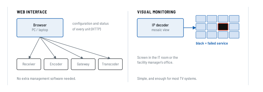
Figure 3. Device web-interface status and visual service monitoring, reproduced from IPTV Headend Planning Guide, 2nd edition (2026), Figure 24.1, p. 72.
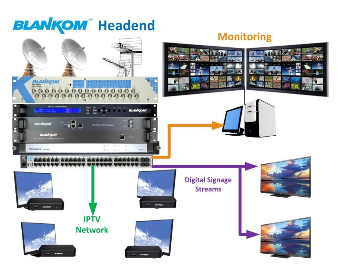
Figure 4. Historical headend and multiviewer illustration reproduced from source-guide Figure 24.2, p. 73. Product images are source examples, not a current bill of materials.
06 · TURN THE DESIGN INTO AN OPERATING PROCEDURE
Define who owns each part of the response
The source redundancy checklist explicitly asks for “monitoring, alarms and who responds to them”. It also treats the IPTV installation as a system whose settings should be documented from the planning stage. The operational model below is an editorial structure derived from those requirements; it is not a service-level promise from the source guide.[1, pp. 9, 35, 80–81]
| Operational event | Owner to define | Action to document |
|---|---|---|
| Black / missing service | Facility/IT monitoring role | Confirm scope: one endpoint, one stream, one transponder or complete headend |
| Receiver/process unit fault | Headend operator / service technician | Check active/standby state, configuration and allowed recovery action |
| Dish / LNB / RF degradation | RF/satellite technician | Check measurement points, master/backup state and physical reception path |
| Network distribution fault | Local network integrator / IT | Switch/uplink/VLAN/IGMP checks and escalation boundary |
| Power failure | Site facilities / IT | UPS/PSU status, restart sequence and expected service restoration |
07 · DOCUMENT BEFORE HANDOVER
A maintainable system needs configuration records, acceptance results and room for growth
The planning guide says to document installations and settings from the planning stage, not after commissioning. Its final planning checklist includes monitoring, service agreements, documentation of all settings and rack space reserved for later expansion. The reference case study also records reserved space for additional receiver-streamers.[1, pp. 35, 67, 71, 80–81]
This handover checklist is an editorial engineering tool for the web series. The source guide supports the need for documentation and future expansion, but does not prescribe this exact document set.
08 · TEST THE FAILURE PATHS YOU HAVE SOLD
Acceptance should verify normal service and the agreed recovery behaviour
-
Baseline the normal state
Record healthy RF input, stream output, network delivery, endpoint behaviour and monitoring view.
-
Test only the redundancy mechanisms included in scope
Where safe and practical, simulate the agreed receiver, reception-path or power/network failure and confirm the expected switch-over behaviour.
-
Measure the visible interruption
Do not describe a solution as seamless unless the project acceptance test supports that claim for the actual configuration.
-
Verify fault detection
Confirm the failure appears in the intended web status, multiviewer or other agreed monitoring path.
-
Verify restoration
Check how the system returns to normal after the failed component or path is restored and whether another interruption occurs.
-
Sign off the exclusions
Record failures that the design does not protect against, including upstream source outages and any unprotected local single points of failure.
CUSTOMER REFERENCE
State exactly what the resilience proposal protects—and what it does not
Use this guide in quotations when redundancy, monitoring or operational handover affects the proposed architecture. The quotation itself should specify the protected services, duplicated components, switch-over method, monitoring scope and exclusions.
“The proposed resilience concept protects the failure domains identified in this quotation and does not imply end-to-end 100% availability. Please refer to BLANKOM Engineering Guide 12 for the distinction between N+1, 1+1, reception redundancy, monitoring and operational handover.”
09 · SEND THE RESILIENCE REQUIREMENTS
What to include in your resilience / operations RFQ
Tell us which services matter most, which failures must be covered and what interruption is acceptable.
If you already have a network, UPS or monitoring system, include its topology and the responsibilities of the local IT/integration team.
The request opens the existing IRENIS / BLANKOM enquiry page. Exact redundancy, monitoring and handover scope will be confirmed in the project quotation.
Resilience brief outline
IPTV RESILIENCE / OPERATIONS BRIEF
Site / application:
Critical TV/radio services:
Acceptable interruption:
Required availability target (if defined):
Reception redundancy required:
Protected satellite positions:
Receiver / streamer redundancy:
N+1 or 1+1 preference:
Power / UPS arrangement:
Network redundancy arrangement:
Monitoring method:
Monitoring location:
Who responds to alarms / failures:
Local network integrator:
Spare-equipment policy:
Required acceptance / fail-over tests:
Documentation / handover requirements:
Future expansion:
Known exclusions:
Reference: IPTV System Design - Guide 12, BLANKOM
FAQ
Common resilience and operations questions
Can an IPTV system be 100% redundant?
No. The source guide explicitly states that no TV system is 100% redundant because the complete chain includes upstream broadcaster and satellite elements outside the local system’s control.
What is the practical difference between N+1 and 1+1?
N+1 uses a shared standby unit and requires configuration/switch-over, which causes interruption. 1+1 mirrors the active unit/path and can minimise visible interruption, but it duplicates hardware.
Should every satellite position have dish-farm backup?
Not necessarily. The source guide specifically allows selective protection of the most important satellite positions when budget is limited.
Is monitoring the same as redundancy?
No. Redundancy provides an alternate path or unit. Monitoring detects that something has failed. The source guide recommends combining redundancy with monitoring so staff know when repair is required.
What should be handed over at the end of the project?
The source guide requires documentation of settings from the planning stage and includes documentation in its final planning checklist. This web guide expands that principle into a practical handover checklist covering topology, configurations, test results, ownership and limitations.
SOURCE BASIS
Primary engineering source
This guide reformulates the resilience and operations material in Ralf Riedel’s published 2026 second edition. The failure-domain table, operational responsibility matrix, handover checklist, acceptance workflow, quotation wording and RFQ structure are editorial engineering tools added for the web series. They do not create a universal availability guarantee or a product-specific fail-over specification.
- Ralf Riedel — IPTV Headend Planning Guide, 2nd edition (2026)
Primary scope: Chapter 3, pp. 8–9 for N+1/1+1 redundancy and the architect checklist; Chapter 7, pp. 20–22 for dish-farm redundancy; Chapter 11, p. 35 for documentation from the start; Chapter 23, pp. 67–71 for future expansion and reference designs; Chapter 24, pp. 72–73 for monitoring; Appendix C, pp. 80–81 for the final planning/documentation checklist.
Document reference: BLANKOM-EG-IPTV-12 · Web revision 1.0
IPTV System Design · BLANKOM Engineering Guide Series
- Requirements and ArchitectureGuide 01
- Services, Transponders and Tuner CountsGuide 02
- SAT-IF DistributionGuide 03
- IPTV Headend SelectionGuide 04
- Pay-TV IntegrationGuide 05
- DVB Transport Stream ValidationGuide 06
- EPG / EIT Processing and Receiver ValidationGuide 07
- IPTV Multicast Network DesignGuide 08
- IPTV Stream DeliveryGuide 09
- Local Video SourcesGuide 10
- IPTV Endpoints and ServicesGuide 11
- Resilience and OperationsGuide 12
© 2022–2026 BLANKOM, IRENIS GmbH. All rights reserved. Availability, redundancy and compatibility depend on the complete project architecture and selected equipment. Verify the current product documentation and the project-specific acceptance criteria before specification or purchase.
